Valve bodies are among the most demanding parts a CNC shop can cut. A spool bore must hold roundness and straightness within a few microns over its full length. The seat must seal against pressure with minimal contact force. Port threads must gauge perfectly, because leakage is the one failure nobody forgives. Valve body machining combines precision turning, milling, and careful inspection to make all of those features coexist in one part.
Valve Bodies 101: Spool, Poppet, and Ball Valve Designs
A valve body is the pressure-containing skeleton of a valve. It carries the flow ports, houses the moving element, and provides the mounting interface. In a spool valve, a cylindrical spool slides inside a precision bore, routing fluid between ports as it shifts. Directional control valves in mobile and industrial hydraulics use this layout almost exclusively.
Poppet valves work differently. A conical or ball-shaped poppet lifts off a matching seat to admit flow, then a spring or system pressure returns it to seal. Check valves and cartridge valves follow this pattern. Ball valve bodies, meanwhile, house a rotating ball with a through-bore. Quarter-turn operation makes them the default for isolation service in plumbing, gas, and process lines. Each layout imposes its own valve body machining priorities.
Mounting interfaces vary just as widely. Cartridge valves press into standardized cavities, sectional bodies bolt into stacks, and inline bodies carry flanged or threaded ports. Because the body is the only part every other component references, valve body machining must hold every interface to one datum scheme. Miss that, and the valve may seal internally yet still misalign with its manifold or piping.
The Critical Features in Valve Body Machining
In valve body machining, spool bores set the highest bar. The bore must stay round and straight along its full length, because the spool-to-bore clearance often runs at a few microns. Any ovality lets fluid bypass, and any taper shifts the spool’s neutral position. Shops hold these bores with finish boring and then honing, checking roundness and straightness with air gauges or bore gauges between operations. Surface finish matters equally: a honed spool bore typically runs below Ra 0.4 µm to keep friction low and leakage consistent.
Seat geometry decides sealing performance in poppet and ball designs. The seat angle, surface finish, and concentricity to the flow axis determine whether the valve seals at low pressure with minimal actuation force. A seat that sits even slightly off-center leaks at one edge. Machining seats therefore calls for rigid tooling, fine feeds, and often a final lapping or ballizing step.
Port threads and sealing faces form the third critical family. Whether the design uses NPT, SAE, or BSPP ports, the threads must gauge correctly and the sealing surface must carry its O-ring or washer without weeping. Counterbore depth, pitch diameter, and face flatness all feed into leak-free assembly. Because these features also define how the valve mounts into the wider system, their position tolerance matters too.
Matching the Material to the Service
Material selection starts with the fluid and the pressure. Aluminum bodies dominate mobile hydraulics, where weight matters and pressures stay moderate. Brass suits water, fuel, and pneumatic service because it machines fast and handles those fluids well. Carbon steel bodies serve high-pressure hydraulic and oilfield equipment. Stainless grades, especially 316, take corrosive, sanitary, and offshore duty where the fluid would attack anything cheaper.
Each alloy changes the valve body machining plan. Aluminum wants sharp tools and strong chip evacuation to avoid built-up edge. Brass is the freest-cutting of the group and rewards high speeds. Stainless demands rigid setups, lower speeds, and careful heat management. For brass parts, our brass CNC machining page details the alloys and tolerances we hold. The same selection logic applies to surface treatment, since plating or passivation must suit both the alloy and the fluid.
How Turning and Milling Combine in Valve Body Machining
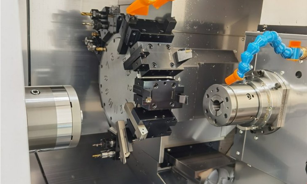
Most valve bodies start on a lathe. Round bar becomes a near-net shape, with spool bores rough-turned from one end and seats faced in the same setup. Turning establishes the rotational features that everything else references. It also produces the spools, poppets, and stems that later mate with the body, so both halves of every sealing pair come from controlled, matching processes.
Milling takes over for the non-round features. Port bosses, mounting flanges, and multi-face port layouts run on a machining center, often a five-axis machine so several faces finish in one clamping. Cross-drilled passages connect ports to the main bore, and tapping completes every thread. XAP Precision runs both processes under one roof, with our CNC turning service handling the round features and mating components. Valve body machining succeeds when turning and milling share one datum strategy.
Process planning deserves equal attention. Shops that rough every body first, then finish the bores in one controlled pass, hold size far better than shops that bounce parts between operations. Heat from roughing needs time to dissipate before finish cuts, or bores drift after machining. First-article inspection on every feature, including gauged threads, catches setup errors before they repeat across the lot.
Inspection and leak testing close the loop. Critical bores get checked for size, roundness, and finish before assembly. Cross-drilled passages need the same care, since a burr left at an internal intersection breaks loose later and scores the spool. Finished valves then undergo pressure testing, either with air under water for bubble detection or with hydraulic fluid at rated pressure. Valve body machining contracts should state test pressure and hold time on the drawing so the acceptance standard is never in doubt.
Frequently Asked Questions About Valve Body Machining
What tolerance does a spool bore typically hold?
Spool-to-bore clearance commonly runs between 3 and 10 microns per side, depending on pressure and valve size. Holding that demands finish boring followed by honing, with gauging between operations. If your design targets a tight leakage class, state the required clearance band on the drawing so process planning can match it.
Which material is best for a high-pressure hydraulic valve body?
Carbon steel is the default for high-pressure hydraulic bodies, since it tolerates high bore stresses and accepts heat treatment. Stainless 316 takes over where corrosion or hygiene governs. Aluminum suits moderate-pressure mobile circuits where weight savings justify its lower pressure ceiling. Share your working pressure and fluid, and the material choice follows quickly.
Can one shop machine both the valve body and the spool?
Yes, and there is a real advantage. Bodies and spools cut in the same shop share gauge discipline, so the mating clearance stays consistent lot to lot. Valve body machining paired with in-house turning of spools and stems also shortens lead time and keeps one supplier accountable for how the pair fits.
Get a Free Quote on Valve Body Machining
Tight bores, true seats, and gauge-perfect threads leave no room for guesswork. XAP Precision machines valve bodies in aluminum, brass, carbon steel, stainless, and engineering plastics under ISO 9001 quality management. Send your drawing today for a free quote and free DFM feedback on bore, seat, and port callouts. Contact us to get started.