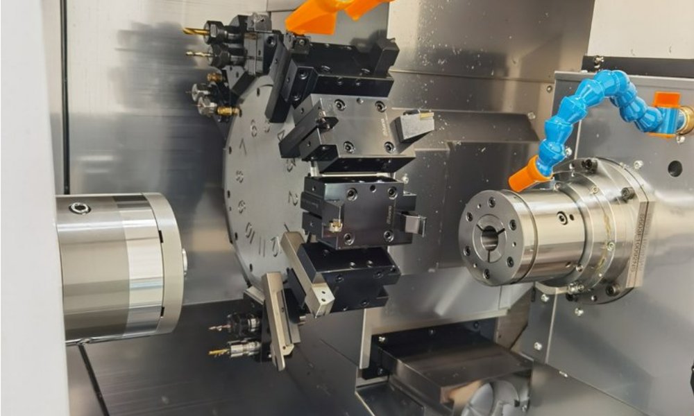
A hydraulic manifold replaces a tangle of hoses, tubes, and fittings with one block of machined metal. Fluid routes become holes drilled and bored through the block, and valves mount directly to machined ports on its faces. Done well, the result leaks less, weighs less, and assembles in minutes instead of hours. Reaching that result depends entirely on hydraulic manifold machining: deep intersecting bores, precise port threads, and disciplined design rules.
What a Manifold Does, and Why Machining Decides Its Reliability
Every hydraulic system moves fluid from a pump to actuators through a network of channels. Traditional plumbing builds that network from external pipe and hose assemblies. Each connection then becomes a potential leak point and a recurring maintenance task. A manifold internalizes the network instead. Channels become intersecting holes inside solid metal, sealed at their ends with plugs.
The benefits compound quickly. Fewer external joints mean fewer leak paths and a smaller overall envelope. Flow distances shorten, which cuts pressure loss. Service improves too, because valves and sensors mount straight onto standardized ports. However, all of these gains rest on machining quality. A bore that drifts off axis misses its intersection. Likewise, a port face that lacks flatness leaks at the seal. That is why hydraulic manifold machining sits at the critical end of the build.
Critical Features in Hydraulic Manifold Machining
Deep intersecting bores define the core challenge. A typical block needs holes driven many diameters deep, meeting other holes at exact locations. Intersection accuracy matters because flow paths must connect fully, and a missed intersection creates dead legs or internal bypass. Gun drilling and peck drilling keep long bores straight. Meanwhile, five-axis positioning lets one setup reach multiple faces without re-fixturing error. In hydraulic manifold machining, this accuracy is the product, not a bonus.
Port threads form the second critical family. SAE straight-thread O-ring ports dominate high-pressure mobile hydraulics. NPT tapered threads still appear in legacy industrial designs, while BSPP parallel threads serve much of the international fleet. Each standard brings its own thread form, sealing method, and counterbore requirements. Tapping must hold gauge limits tightly, because over-tapped ports leak past the seal and under-tapped ports split fittings.
Leak-free performance is the acceptance bar. Internal leakage between channels can defeat a valve’s function entirely. External leakage creates safety incidents and environmental reports. As a result, serious shops inspect bore intersections, verify threads with calibrated gauges, and pressure-test finished blocks before shipment. Surface finish inside sealing bores matters just as much, since O-rings need a controlled roughness to seat without extruding.
Design Rules for Reliable Hydraulic Manifold Machining
Good manifold design starts with bore spacing. Parallel bores need enough wall between them to hold pressure without ballooning or breaking through. Thin walls between high-pressure channels turn into fatigue cracks over millions of pressure cycles. Designers should also minimize plug holes. Every drilled passage needs an entry, and each opening becomes a plug, a seal, and one more potential leak point.
Sharp intersections deserve attention too. Where two bores meet, the shared edge can be knife-thin, and debris collects in the crescent gap. Small chamfers or stepped bore layouts reduce stress concentration and smooth the flow path. Avoid sudden diameter changes inside high-velocity passages as well. Hydraulic manifold machining gets measurably easier when designers give bores straight approaches and generous relief at counterbore bottoms.
Finally, hydraulic manifold machining rewards designs that respect tool access. Port faces need enough flat area around each port for the seal boss and for wrench clearance on adjacent fittings. Label ports on the drawing and, where possible, on the block itself. A DFM review before release catches most access problems while they are still cheap to fix.
How Shops Execute Hydraulic Manifold Machining Step by Step
Hydraulic manifold machining begins with a sawn, squared block, stress-relieved first when the alloy calls for it. The first operation mills all six faces flat and parallel, because every later measurement references those datum faces. Deep holes follow, drilled with peck cycles or gun drills depending on depth and diameter. Shops sequence the bores deliberately so each one breaks through into a finished partner hole.
Tapping and counterboring come next, with gauging on first articles. Port faces are then finish-milled and deburred, since burrs left at internal intersections contaminate the system later. Cleaning matters more than many buyers expect. Chips trapped in a gallery will surface later as pump damage, so blocks go through wash and inspection before any plug or valve mounts. Pressure testing closes the loop. XAP Precision follows this exact sequence on manifold projects every week.
Material Selection: Aluminum, Carbon Steel, and Ductile Iron
Material choice follows pressure and environment. Aluminum manifolds machine quickly, weigh little, and suit low-to-medium pressure circuits such as mobile auxiliaries and test stands. Carbon steel handles high-pressure industrial and mobile circuits, tolerating higher bore stresses and accepting welded repairs when needed. Ductile iron serves very high-pressure, high-volume applications where a casting plus finish machining keeps cost down. Stainless grades enter wherever corrosion governs, such as food processing and offshore equipment.
Whatever the alloy, the cutting strategy must match it. Steel blocks demand rigid setups and careful chip control in deep holes, while aluminum rewards high-speed peck drilling. XAP Precision machines manifold blocks in aluminum, carbon steel, stainless steel, and engineering plastics. Our steel CNC machining guide covers the alloys we run daily, and our CNC turning service supplies the plugs, adapters, and port fittings that complete the assembly.
Frequently Asked Questions About Hydraulic Manifold Machining
What pressure can a machined manifold block handle?
There is no single number. Capacity depends on material, wall thickness between bores, and bore diameter. Aluminum blocks suit low-to-medium pressure circuits, while steel and ductile iron handle high-pressure mobile and industrial duty. Share your maximum working pressure and circuit layout, and the block geometry can be designed and verified around it.
Can a manifold replace existing hoses and tube plumbing?
Yes, and that is the most common reason buyers redesign. A manifold consolidates hoses, tubes, and fittings into one drilled block with valves mounted on its faces. Leak points drop, the envelope shrinks, and assembly time falls. The usual first step is a DFM review of the existing schematic to find which connections the block can absorb.
How do shops verify that a manifold is leak-free before shipment?
Shops combine several checks. Thread gauges verify every port, and intersection inspection confirms internal passages connect as designed. The finished block then undergoes pressure testing at or above rated working pressure with leak-down monitoring. For critical circuits, hydraulic manifold machining contracts can also require flow testing to confirm pressure drop across each path.
Get a Free Quote on Your Hydraulic Manifold Machining Project
Manifold projects reward early collaboration between designer and machinist. As a hydraulic manifold machining partner, XAP Precision produces blocks in aluminum, steel, stainless, and plastic, with turned plugs and adapters made in the same shop under ISO 9001 quality control. Send your model or port schematic today for a free quote and free DFM feedback on bore layout and port standards. Contact us to start the review.