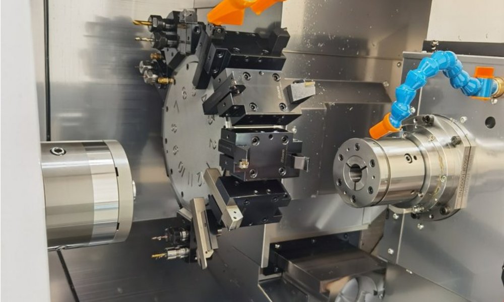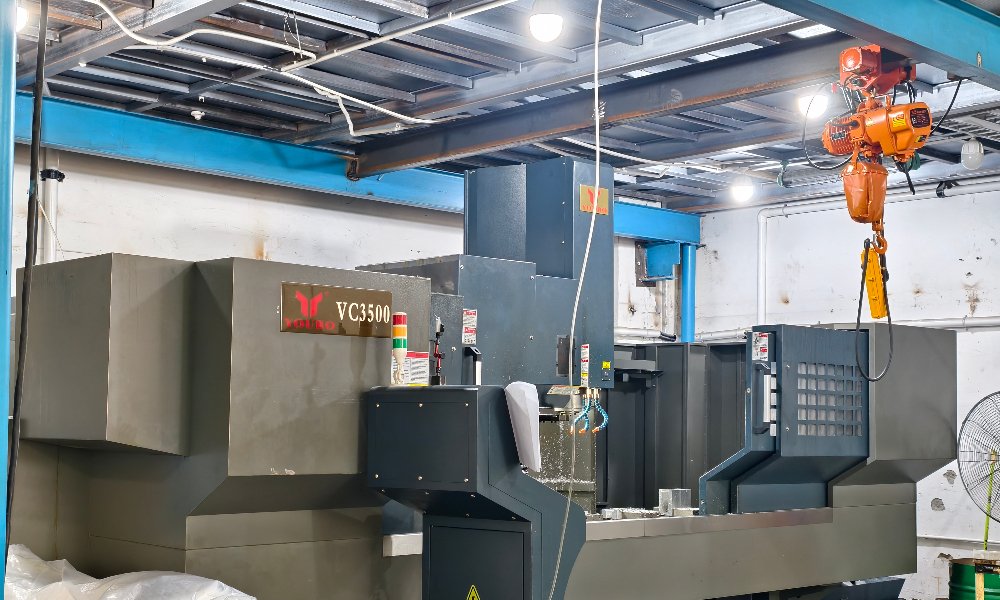
High speed machining has moved from a niche technique to a default strategy in modern CNC shops. At XAP Precision we use it every day to cut harder materials faster, hold tighter tolerances, and produce parts that need less secondary work. The approach reverses old assumptions about how a cutter should meet the metal. Instead of forcing big chips off slowly, it removes many thin chips quickly while keeping forces low and heat out of the part. This guide explains what actually happens during high speed machining, when the process pays off, and how we plan toolpaths and tooling so your parts ship on time and within budget.
What Sets High Speed Machining Apart
Traditional milling relies on a deep cut and a slow feed. High speed machining reverses that logic. The spindle runs much faster, the feed rate rises sharply, and the cutter takes a shallow bite. Rather than sinking the tool halfway into the material, we typically run radial depths from five to twenty percent of the cutter diameter while axial depth can stay large. The heat that a slow heavy cut would push into the part is instead carried away inside those thin chips. For aluminum that means less warping and a truer part after the clamps come off. For hardened tool steel it means you can cut at fifty to sixty HRC with a surface that once required grinding or electrical discharge. If you want a broader overview of our capabilities, our CNC milling service guide covers spindle ranges, control systems, and the materials we run daily.
The Three Core Principles
Every reliable program rests on three interlocking ideas. First, high spindle speed. Carbide cutting edges work best inside a certain surface-speed window, and faster rotation keeps you there even on small diameter tools where a modest RPM would leave the edge barely moving. Second, high feed per tooth. Feeding aggressively protects the edge by pushing it through the cut before heat soaks in, and it shortens cycle time on long runs. Third, light radial engagement. A shallow side bite drops cutting force dramatically, which reduces deflection and lets the machine track the programmed path more closely. These three principles must move together. Pushing only spindle speed without matching feed and engagement simply wears the tool and adds nothing. Tuned as a set, they turn a fast machine into a productive one that holds size from the first part to the last.
Benefits You Can Measure on the Shop Floor
Faster material removal is the obvious gain. On many aerospace and mold jobs, a cycle that once took six hours now finishes in ninety minutes, which frees the machine for the next order. Surface finish improves at the same time, because small radial cuts and tight stepovers leave a finer scallop on the wall and floor of the pocket. Tool life also extends when forces stay moderate and most of the heat leaves with the chip rather than the edge. Dimensional accuracy holds better on thin and long parts because less force pushes the wall away from the cutter during the final pass. Customers often find they can drop a separate finishing operation entirely, which cuts handling and shortens lead time. These gains are why high speed machining is now our default first consideration on most milling work. For round components the same logic applies, and our CNC turning service for round parts uses matched high-feed strategies where the geometry allows.
Toolpaths That Make the Strategy Work
Path design decides whether this process succeeds or fails. We avoid sharp corner moves that would jerk the machine off its feedrate and stall the spindle. Instead we roll through corners with smooth arcs, keep engagement consistent around the tool, and use ramp or helical entries rather than harsh straight plunges. Stepover stays tight to control scallop height on finished surfaces, while stepdown can run deeper than usual because the radial load per pass is small. Continuous engagement means continuous cutting, and continuous cutting means stable temperature and stable size. We also watch the transition between roughing and finishing so the last few passes remove only a thin, predictable layer. A well-planned path is worth more than an expensive machine, because it is the path that governs force, heat, and accuracy in every program we ship.
Tooling and Machine Requirements
Standard end mills do not unlock the full value here. We use solid carbide tools with polished flutes to shed chips cleanly, and we favor short stick-out to prevent chatter at high RPM. Coatings such as aluminum-titanium nitride or nano-layer films protect the edge in sticky alloys and hard steels alike. On the machine side we need a rigid spindle rated for the speeds we run, linear drives or high-dynamics rotary axes, and a control that reads ahead to slow smoothly into corners instead of overshooting them. Coolant delivery matters just as much: through-spindle coolant at high pressure clears chips from deep pockets before they are recut and damage the finish. If your part geometry uses several angled faces, our 5-axis CNC machining service pairs well because a tilting head keeps the tool at an ideal cutting angle throughout. This kind of complete, rigid setup is exactly what high speed machining rewards.
When to Choose This Process
This strategy shines in a few specific situations. Thin-wall parts benefit because cutting force drops, so walls do not bow away from the cutter, a topic we cover in detail in our thin wall machining article. Hardened steels above about forty-five HRC become practical to mill instead of grind. Aluminum aerospace structures cut faster and stay flatter after unclamping. Deep pockets that would chatter with a conventional approach clear well with light radial passes and steady engagement. On the other hand, heavy roughing on a forgiving block of mild steel can still be cheaper with a large slow tool, and simple prismatic parts may not need the setup time at all. The right call depends on material, geometry, and tolerance. Send us your STEP file and we will tell you when this process helps and when a simpler strategy makes more sense for your budget and volume.
Is high speed machining the same as simply running a spindle fast?
No. Spindle speed is only one input. The real strategy combines fast rotation, aggressive feed, and shallow radial engagement inside a balanced toolpath. A machine can spin at twenty thousand RPM and still cut poorly if the feed and stepover are wrong. The process works when all three settings move together, so we tune them as a single set rather than adjusting one value at a time.
Which materials respond best to this strategy?
Aluminum, copper, and brass gain a large cycle-time reduction because they respond well to high feed and small engagement. Hardened tool steels also benefit, because the method lets a carbide end mill remove material at a rate once possible only with grinding or electrical discharge. Stainless steels and nickel alloys are workable but demand careful feedrates and coolant to avoid work hardening. We match the setup to the exact alloy and heat-treatment state shown on your drawing.
Does this process wear out my cutting tools faster?
Usually the opposite happens. Because cutting forces stay low and most heat leaves with the chip, the cutting edge sees less thermal cycling and less mechanical shock on each revolution. Tool life often doubles compared with conventional milling on the same part geometry. There are exceptions in gummy alloys where the wrong coating can cause built-up edge, so we validate parameters on the first setup before committing to a full production run.