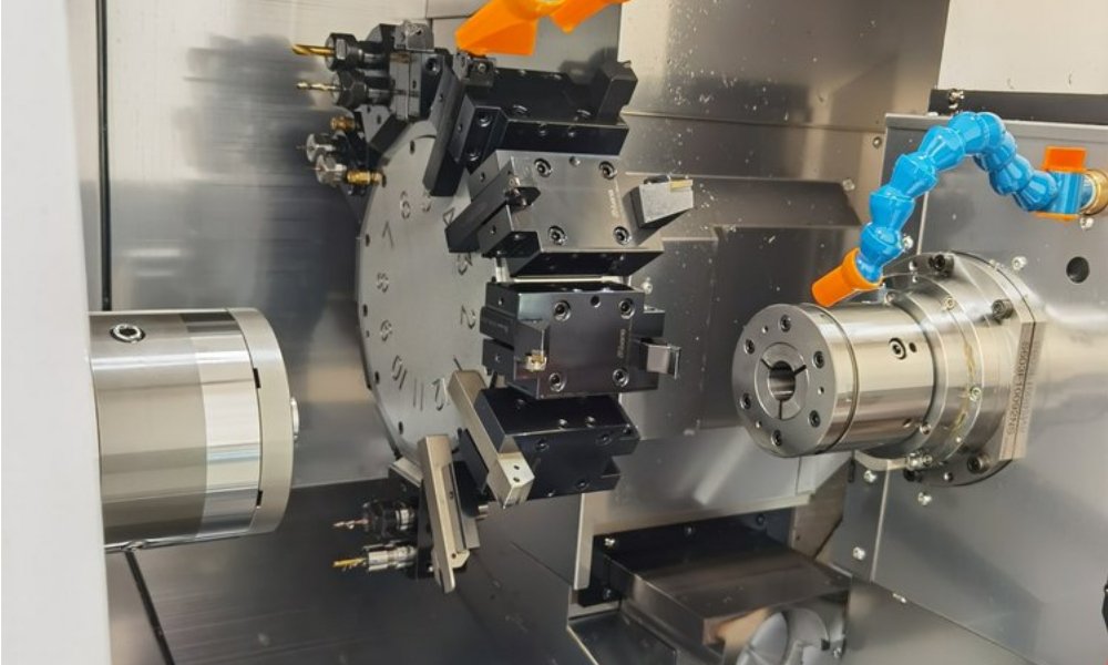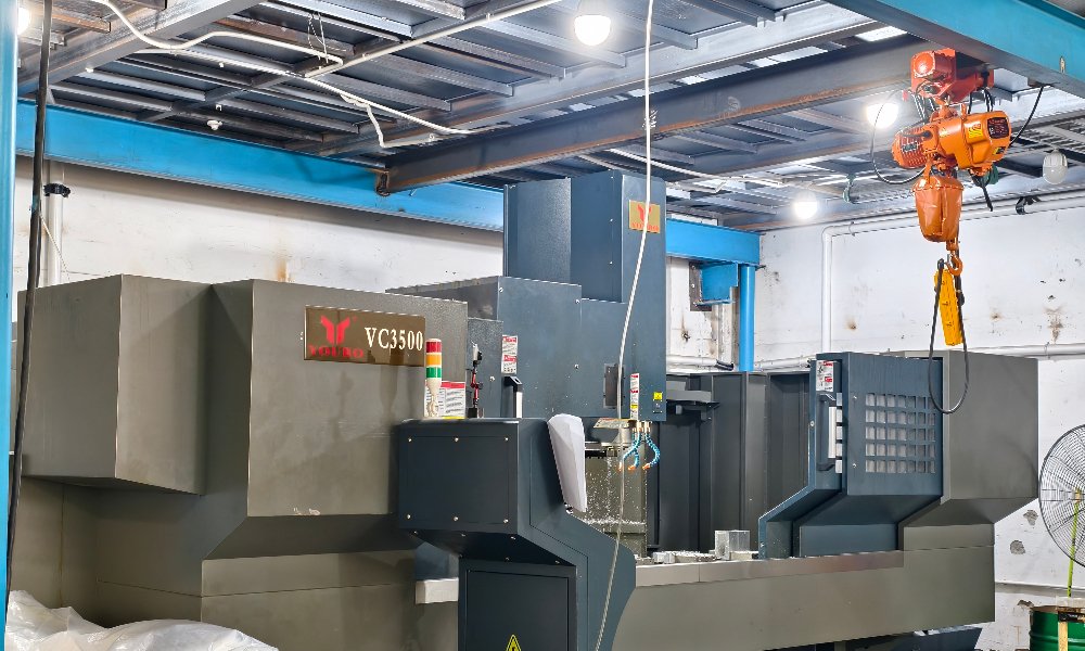
When an electric motor moves from concept to production, the enclosure around it becomes a precision component in its own right. Motor housing machining covers the milling, turning, and boring operations that create stator bores, bearing seats, mounting faces, and cooling fins from solid aluminum or steel. For EV programs and industrial motor lines alike, the quality of this machining decides how quietly the motor runs and how long the bearings last.
Cast housings dominate high-volume production, yet casting tooling demands months of lead time and heavy upfront cost. Motor housing machining fills the gap before tooling is justified, and it also serves applications where volumes stay modest and tolerances stay tight. Understanding the critical features, material choices, and machining strategies behind these parts helps you specify them with confidence.
What Motor Housing Machining Has to Get Right
A motor housing looks simple from the outside. In practice, several features interact, and each one deserves attention during design review.
The stator bore is the most demanding feature. Motor housing machining must hold this diameter tightly, because the stator stack presses into it at h6 or h7 fits. Runout relative to the bearing seats must stay within a few hundredths of a millimeter. Any eccentricity turns into magnetic pull, vibration, and audible noise. As a result, shops bore this feature in a single setup whenever possible.
Bearing seats at both ends of the housing locate the rotor. They carry tight diameter tolerances and fine surface finishes, typically Ra 1.6 or better. These seats also need clean shoulders for axial location. Because castings can include hard spots, boring and turning passes must stay stable across interrupted sections and laminations.
Mounting faces seal the deal on assembly. Flatness on the mating flange prevents leaks and misalignment, while dowel holes locate the housing to the end bells or gearbox. In addition, terminal box bosses and cable gland threads need clean, burr-free machining.
Finally, cooling fins multiply the housing surface area and reject heat from the windings. They look decorative, but their geometry drives real machining decisions, as the fin section below explains.
Aluminum vs Steel: Choosing the Housing Material
Aluminum leads the field for machined motor housings. Alloys such as 6061-T6 and A380-style blanks cut fast, weigh little, and conduct heat well. The conductivity helps move winding heat out to the fins, while the low mass suits EV traction motors and servo applications. You can explore more in our guide to aluminum CNC machining.
Steel housings earn their place where strength and stiffness dominate. Carbon steel suits large industrial frames with heavy press-fit loads. Stainless steel appears in washdown and food-grade environments, where corrosion resistance is non-negotiable. The trade-off is weight and slower machining, so steel housings usually land on fixed industrial equipment rather than mobile platforms.
Beyond material selection, think about how the part is made. Motor housing machining from billet holds tighter concentricity than a rough casting and needs no core prints or draft angles. For prototypes and low volumes, that freedom often outweighs the raw material cost.
How Thin Fins Get Machined Without Chatter
Cooling fins are tall, thin, and eager to vibrate. When a cutter pushes against a fin, the fin flexes, and chatter marks or broken tools can follow. Successful fin machining starts with strategy rather than brute force.
First, shops run high spindle speeds with light stepover and climb milling. This combination keeps cutting forces low. Second, they finish fins after all heavy pocketing, so the housing walls still have stiffness during roughing. Third, toolpaths often spiral around the fin field instead of plunging between fins.
Coolant choice matters too. Air blast or minimum-quantity lubrication clears chips without letting aluminum weld onto the cutter. Sharp, polished-flute tools reduce that sticking tendency further. In addition, programming the finishing pass in one continuous move keeps a uniform appearance across the whole fin array.
XAP Precision applies these motor housing machining strategies across a wide range of sizes and fin patterns. When a design adds compound angles or ports on multiple faces, our 5-axis CNC machining capability completes the part in fewer setups and holds bore-to-face relationships more reliably.
Why EV Startups Rely on Motor Housing Machining
Electric vehicle programs change fast. A motor team may revise the stator bore diameter, fin height, or mounting pattern after every dyno cycle. Casting tooling cannot keep up with that pace, since each design change risks expensive mold rework.
Motor housing machining removes that constraint. A revised CAD model can become a new housing in days, which lets teams test bearing preload changes or packaging updates without waiting for tooling. In addition, the same approach scales across variants. A startup running three motor sizes can adapt one machining program family instead of funding three mold sets.
The economics stay favorable longer than many buyers expect. In practice, motor housing machining from billet or extruded blanks makes sense through prototype builds, pilot fleets, and niche production runs. Once annual volumes truly justify it, a cast design can inherit the features you validated on machined parts.
DFM Tips for Motor Housing Machining
A few design habits pay off quickly. Keep fillet radii generous at fin bases, because a sharp internal corner demands a tiny tool and slow feed rates. Use standard tool sizes for fin spacing where possible, and avoid fin gaps narrower than the cutter that must form them.
Next, locate all critical features from one datum. When the stator bore, bearing seats, and mounting face reference the same setup, the shop can hold concentricity without re-fixturing. Also, specify tolerances only where function demands them. A fin height held to plus or minus half a millimeter costs little, while a cosmetic face held flat costs plenty.
Finally, share your 3D model with the machine shop early. A thorough DFM review walks through the same checks we apply to every housing quote, from tool access to workholding.
Frequently Asked Questions About Motor Housing Machining
What tolerances can I expect on a machined stator bore?
A quality motor housing machining process holds stator bores to h6 or h7, roughly within 0.01 to 0.025 mm of the nominal diameter. Runout to the bearing seats typically stays under 0.03 mm. Exact capability depends on bore size, housing material, and how the part is fixtured during boring.
Is it cheaper to machine a housing or cast one?
Casting wins at high volumes once tooling cost is amortized. Below that threshold, motor housing machining costs less overall because it avoids mold investment, needs only days of lead time, and absorbs design changes freely. Most programs machine prototypes and early builds, then evaluate casting after volumes are proven.
Can you machine cooling fins that are very thin?
Yes. With high-speed light-depth passes, climb milling, and the right fixturing, fins under one millimeter thick can be machined cleanly. The practical limits depend on fin height and spacing, so share your model early. We will review fin geometry for chatter risk before quoting.
Start Your Motor Housing Project
A well-machined housing protects everything inside the motor, from bearing life to acoustic performance. XAP Precision is an ISO 9001 certified manufacturer in China offering 3, 4, and 5-axis CNC milling, turning, and rapid prototyping for motor components in aluminum, steel, and more.
Upload your housing model today and receive free DFM feedback plus a detailed quote. Contact us to get started.