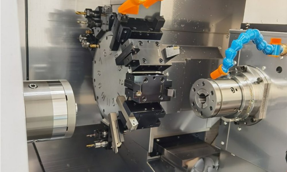
Photonics systems live and die by alignment. Optical mount machining produces the precision brackets, posts, and stages that hold lenses, mirrors, and detectors in position. These parts must deliver micron-level repeatability for years. Whether the part serves a lab fixture or ships inside an instrument in modest volume, machining is the only practical way to make it.
This article covers what stability really demands and how materials shape the design. It also explains the kinematic principles behind adjustable mounts and the surface quality expectations that separate optical-grade parts from ordinary machined hardware.
What Micron-Level Stability Demands from a Mount
An optical mount must resist three enemies. Deflection under load shifts the beam path. Thermal growth moves components as the lab temperature drifts. Assembly stress relaxes slowly, and the alignment drifts with it. Every design decision should attack at least one of these.
Stiffness comes first. Generous section thickness and symmetric rib layouts beat slender geometry. In optical mount machining, the mounting interface should also be cut in the same setup as the optical bore whenever possible. That practice keeps perpendicularity between the bore axis and the base within a few microns.
Feature tolerances follow. Hole position and bore-to-face relationships commonly run between 5 and 15 microns on optical hardware. Holding those numbers in one setup is where our 5-axis CNC machining capability earns its keep. A single clamping preserves every geometric relationship, with no re-fixturing error.
Fine adjustment threads complete the picture. Threads with 0.25 to 0.5 mm pitch translate a fraction of a turn into a few microns of motion. Optical mount machining must cut them cleanly. Sharp tooling, moderate speeds, and consistent parameters keep every mount adjusting the same way.
Materials: Aluminum, Stainless Steel, and Specialty Alloys
Aluminum is the default material in optical mount machining. Alloys like 6061 and 7075 machine cleanly and accept black anodize, which cuts stray reflections inside an optical path. Hard anodize adds measurable coating thickness, though. So specify unanodized dimensions on mating features or budget for it.
Stainless steel suits vacuum hardware and corrosive environments. It machines slower and weighs more. Yet its stiffness and low outgassing after proper finishing make it the choice for chamber feedthroughs and UHV fixtures. In addition, 316L passivates well, which matters for cleanroom instruments.
Specialty alloys serve special jobs. Invar is a nickel-iron alloy with very low thermal expansion. It appears in interferometers and metrology frames where dimensional drift must approach zero. The alloy machines slowly and needs care with heat input, but nothing standard beats it for thermal stability. Brass also earns a role in fine adjuster screws and kinematic balls, where its machinability and wear behavior shine.
Kinematic Design and Fine-Thread Adjustment
Kinematic design locates a part with exactly the constraints it needs and no more. The classic 3-2-1 principle places three contact points on one face, two on a second, and one on a third. That arrangement removes all six degrees of freedom without over-constraint. Over-constrained mounts bend during assembly and drift with temperature, so kinematic restraint avoids both problems.
In practice, many mounts pair matching grooves with ball contacts. A v-groove constrains two directions, a flat constrains one, and a spherical cup constrains the rest. The contact geometry stays deterministic, so the mount returns to the same position after every disassembly. That behavior is the definition of repeatability.
Adjustment relies on fine-pitch threads and spring preload. A 0.25 mm pitch screw produces roughly 0.7 microns of travel per degree of rotation, which makes graduation rings meaningful. Spring loading removes thread backlash, so the contact point stays defined in one direction.
Optical mount machining supports all of this directly. Groove profiles, ball seats, and fine threads must hold tight form tolerances. Thread milling generally gives more consistent results than tapping on fine pitches. Small precision components like adjuster screws also fit Swiss-type turning well. We describe that process in our guide to CNC Swiss-type lathe machining.
Surface Quality and Cleanliness Standards
Optical mount machining must leave no raw surfaces, because hardware sheds particles when surfaces stay rough. Machined faces should reach Ra 0.8 to 1.6 on functional areas, with every edge deburred or lightly broken. Sharp corners and burrs are particle sources, and particles on a mount eventually find the optic.
Anodize helps as well as protecting. A sealed anodic layer locks the aluminum surface, reduces particle generation, and cuts reflectance. For vacuum mounts, skip anodize and specify electropolished stainless instead, since bare metals with polished surfaces outgas less.
Cleanliness follows industry practice in stages. Parts are washed and degreased after machining, dried, then bagged in low-particulate packaging. Specify the cleanliness class to match where the mount will live. A teaching lab needs far less than a semiconductor inspection tool, and paying for over-specification wastes budget.
Why Low-Volume Programs Fit Optical Mount Machining
Photonics programs iterate constantly. A mirror mount may go through three revisions before the optical layout freezes. No tooling process can absorb that pace. Optical mount machining from solid stock delivers revision one this week and revision three next month.
Volumes fit too. Instruments shipping in hundreds or a few thousand units per year rarely justify casting or molding. They also demand precision those processes cannot hold. For these quantities, optical mount machining beats every tooling alternative. Machined mounts serve everything from one-off lab fixtures to steady production demand across research labs and instrument OEMs.
XAP Precision supports this workflow with an ISO 9001 quality system, inspection reports, and DFM feedback on every quote. Bring us a mount that mixes fine threads, tight bores, and thin walls. We will sequence those features before quoting, not after.
Frequently Asked Questions About Optical Mount Machining
What tolerances are achievable on machined optical mounts?
Bore diameters and hole positions can routinely hold within 5 to 15 microns. Fine threads with 0.25 mm pitch are standard. Tighter values are possible on critical features after review. Share your drawing early so we can plan setups around the tightest callouts.
Why do so many optical mounts come black anodized?
Black anodize lowers surface reflectance, which suppresses stray light around sensitive optics. It also seals the aluminum, reducing corrosion and particle generation over the life of the mount. For vacuum mounts, however, bare or electropolished stainless is usually preferred over anodized coatings.
Can you produce just a few mounts for a lab setup?
Yes. Low-volume optical mount machining is a core part of our work, from single prototype fixtures to small batches for instruments. There is no minimum order quantity barrier, and each batch ships with dimensional inspection so your alignment data stays trustworthy.
Build Your Optical Hardware with Confidence
Alignment holds when the mount is stiff, deterministic, and machined to the tolerances the optics demand. XAP Precision is an ISO 9001 certified manufacturer in China. We offer 3, 4, and 5-axis CNC machining, Swiss-type turning, and rapid prototyping in aluminum, stainless steel, and specialty alloys.
Send your mount drawings for free DFM feedback and a precise optical mount machining quote. Contact us today.