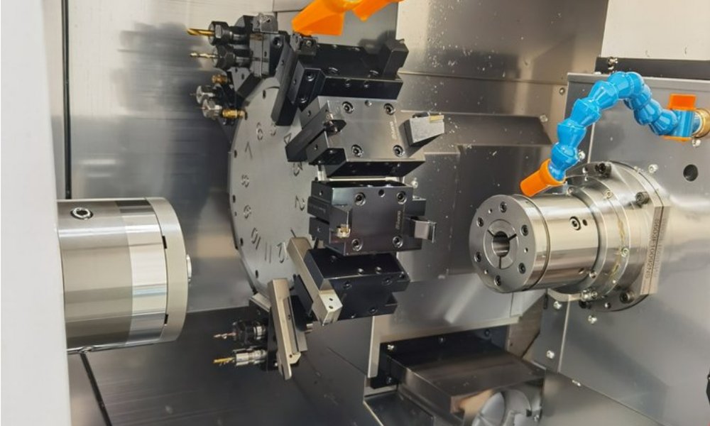
When a feature shrinks below one millimeter, the ordinary rules of milling stop applying. Cutter diameter, chip thickness, and spindle runout all become critical, and a fraction of a degree of temperature change can move a wall out of tolerance. This is why micro machining is treated as its own discipline rather than simply small three-axis work. At this scale the margin for error nearly disappears, and every choice from tool geometry to fixturing must account for forces far smaller than those on a normal part. At XAP Precision we run micro machining for medical devices, connectors, optical components, and miniature mechanism parts, and this guide walks through what changes at small scale and how we plan for it.
The Scale That Defines Micro Machining
Micron-level tolerances dominate the drawing. A tolerance that reads as loose on a large part can be the entire allowable band on a small one. Cutting edges measured in tens of microns must stay true through a run, so a tool that would wear acceptably on a bigger job becomes unusable here. Chips are so thin that they can bend rather than break, wrapping around the flute instead of clearing. Spindle runout matters far more because it is proportionally large against a hairline tool, and any wobble is felt across the whole diameter. None of this is guesswork; the general craft of precision machined parts becomes far more demanding once the geometry shrinks to a few tenths of a millimeter across.
Tiny Tools That Break Easily
We routinely machine with single-flute and two-flute carbide tools under half a millimeter in diameter, some down to a tenth of a millimeter. These cutters snap if you treat them like standard tools, so we use tiny depth increments and gentle ramp entries that keep the load on the edge minimal. Stick-out must be as short as possible, because a long slender tool both deflects and resonates under the smallest side force. Handling is its own challenge: a dropped micro end mill or a single speck of debris in the holder can destroy a tool before it ever touches the part. For that reason we use dedicated holders with very low runout and inspect each edge under magnification before it is cleared for a real cut. Micro machining leaves no room for hesitation, because a single moment of rubbing rather than cutting is enough to snap the edge.
Spindle Speed, Deflection, and Heat
Because the tools are so small, they must spin very fast to reach a useful cutting speed, since a tiny diameter needs high RPM just to move the edge through the material at a reasonable rate. Yet speed alone is not enough. Deflection is a constant enemy, and a light cut that would be negligible on a large part can push a thin wall completely out of position here. Heat is another challenge: even a small amount of friction warms the workpiece, and thermal expansion moves features by more than the tolerance band allows. We manage this with conservative feeds, minimal but precisely aimed coolant, a stable ambient temperature around the machine, and predictable toolpaths that keep forces low from start to finish. This balance of speed, stiffness, and thermal control is the heart of micro machining, and it is why the work is rarely a simple copy of a full-size program.
Fixturing and Workholding
Holding a part the size of a grain of rice is not trivial, and standard vises and clamps are far too coarse for the job. We design dedicated fixtures, often using vacuum chucks, micro clamps, or adhesive mounting for very small blanks, so the part is supported right where the cutter acts. Locating datum features can be smaller than a normal indicator tip, so we set up with high-resolution probes and optical comparators rather than dial indicators. Every fixture is planned to avoid over-constraint, because a small part that is flexed during clamping will spring back out of shape the moment the force is released. For components that combine a turned body with tiny features, we coordinate with our CNC turning service for round parts so both operations share the same datums.
How We Plan a Micro Job
Success begins before the first cut. We review the drawing with magnification in mind, flag any feature that falls at the edge of what the process can reliably hold, and suggest small design changes that raise yield without altering function. We then choose a machine with a clean, vibration-free spindle and set the work zone at a controlled temperature so thermal drift does not steal the tolerance overnight. Probing is done with tools light enough not to bend the part, and we build in intermediate checks so a drifting dimension is caught after one cavity rather than after a full batch. This planning is where the real risk is removed from the operation. Because micro machining is unforgiving, we also log the tool offsets, holder runout, and ambient conditions for each job so that a successful setup can be reproduced exactly the next time you order the same part.
Industries That Rely on This Craft
Medical devices are the most visible example: surgical instruments, implant components, and device housings all carry small precise features that must perform reliably in the body. Electronics and connectors need tiny slots, pin bores, and thin walls that stay aligned across only a short distance. Optical and photonics assemblies require housings and mounts held to the micron so lenses sit square in their barrels. Aerospace and defense use miniature mechanisms and sensors, and watch and instrument makers depend on the same skills. Each of these sectors accepts parts only when the process is documented and repeatable, which is why our thin wall machining discipline and careful inspection travel alongside every job we run.
How small a feature can you actually machine?
We regularly produce features down to a few tenths of a millimeter and smaller where the geometry allows, holding tolerances measured in microns. The practical limit depends on the material, the tool availability, and the specific shape you need, with very high aspect ratio tiny slots and bores being the hardest. We review each drawing and tell you honestly which dimensions are achievable and where a slight change would improve yield without affecting the function of the part.
Which materials work best for micro parts?
Stainless steels, titanium, brass, beryllium copper, and aluminum are common, and each behaves differently under a very small cutter. Brass and aluminum machine cleanly and suit prototypes and connectors, while stainless and titanium are widely used in medical work but demand tight control of heat and deflection. Some engineered plastics are also possible with the right setup. We match the tooling and parameters to your chosen grade and its condition.
How do you inspect parts this small?
We use optical comparators, high-magnification vision systems, and touch probes rated specifically for micro geometry. Because contact force can deflect a tiny part, we select inspection methods that avoid bending the very feature being measured. For critical runs we document results against the drawing tolerance on every important dimension, and that inspection record travels with the shipment so you receive proof of conformance rather than a simple assurance.