A drawing without tolerances is only a sketch. Every dimension on a machined part needs an allowable variation band, and that band drives fit, function, and price. That is why a working knowledge of CNC machining tolerances matters to every buyer and design engineer. This guide explains standard tolerance classes, what machine shops can realistically hold, and how to note limits on drawings. You will also see where tight tolerances inflate cost and where you can safely relax them.
What Are CNC Machining Tolerances?
A tolerance defines how much a measured dimension may vary from its nominal value. For example, a drawing that calls out 25 ±0.05 mm allows the finished shaft to measure anywhere between 24.95 and 25.05 mm. CNC machining tolerances cover size, position, and form, including features such as flatness, parallelism, and concentricity.
Tolerances also control how parts fit together at assembly. A clearance fit lets a shaft spin freely in a bore. By contrast, an interference fit locks two parts together with pressure alone. Standard fit designations such as H7/g6 tie hole and shaft limits to shared bands, so parts stay interchangeable from batch to batch.
Choosing those limits is an economic decision as much as a technical one. Loosen too far, and parts rattle, leak, or refuse to assemble. Tighten too far, and you pay for scrap, inspection, and slow machining. The goal is always the widest band that still lets the product function.
Standard CNC Machining Tolerances: ISO 2768 and IT Grades
Most shops do not dimension every feature on a drawing individually. Instead, they machine to a general tolerance stated in the title block. ISO 2768 is the most widely used framework. It defines four classes, m, c, f, and v, running from medium to very coarse. As a result, one note such as “ISO 2768-mK” sets default limits for lengths, angles, and geometric runout across the whole part.
The International Organization for Standardization publishes these documents, along with the IT grade system behind them. IT grades rank individual dimensions from IT01 to IT18, and lower numbers mean tighter bands. For instance, IT7 suits bearing and press fits, while IT12 covers rough structural work. In other words, the IT grade tells your machine shop how precisely each feature must land.
If a print states nothing at all, a responsible shop will ask before cutting metal. At XAP Precision, unnoted work defaults to ISO 2768-mK unless the order says otherwise. That habit keeps CNC machining tolerances predictable and protects both sides from disputes at inspection.
What Tolerances Can a CNC Machine Shop Hold?
Capabilities depend on the process, the tooling, and the condition of the machines. In general, standard 3-axis milling holds about ±0.05 mm on metal parts without special effort. Precision milling and turning reach ±0.01 mm reliably. Meanwhile, Swiss-type lathes and finishing operations such as grinding push toward ±0.005 mm. Holes are usually easier to control than pocket widths, because reamers and boring heads give direct size control. These ranges describe typical CNC machining tolerances for modern, well-maintained equipment.
- Standard milling and turning: ±0.05 to ±0.1 mm, consistent with ISO 2768-m
- Precision features: ±0.01 to ±0.02 mm with controlled setups and inspection
- Swiss-type and ground features: down to ±0.005 mm
- Threads: standard classes such as 6H for internal threads
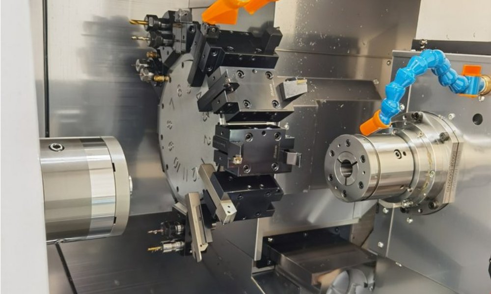
Turning centers often hold tighter bands on round features than mills do on prismatic ones. The part spins against a stationary tool, so diameter control stays consistent cut after cut. That is why bearing journals and seal seats usually start life as turned blanks.
Part size shifts the math as well. A ±0.05 mm band on a 10 mm pin is routine, while the same band across a 600 mm weldment takes real planning. Large parts grow with heat and deflect under clamping. Therefore, sensible CNC machining tolerances scale with part size, exactly as the ISO 2768 tables do.
Factors That Affect Achievable Tolerances
Material choice comes first. Stainless steels and titanium alloys deflect tools and trap heat, so they resist tight work more than free-machining brass or 6061 aluminum. Plastics behave differently again. POM cuts cleanly but heats up and moves, while soft PTFE deforms under clamp pressure. Our material selection guide for custom CNC machined parts covers these trade-offs in depth.
Feature geometry matters just as much. Thin walls chatter, deep holes wander, and slender shafts deflect under cutting forces. In addition, each new setup adds a small location error, so features machined in one clamping hold their relationship best. That is one reason 5-axis work shines on parts with tight datum-to-datum callouts.
Environment rounds out the list. Temperature swings move both the machine and the workpiece, which matters most below ±0.01 mm. Tool wear, spindle runout, and coolant practice all let dimensions drift over a production run. Consequently, holding CNC machining tolerances at the tight end demands monitoring and discipline, not just good machines.
How to Note CNC Machining Tolerances on Drawings
Start with the general tolerance in the title block, for example “ISO 2768-mK” or “±0.1 mm unless otherwise noted”. Then apply specific limits only to critical features, such as a bearing seat at 25 h7. This approach keeps the print readable and the quote honest.
Reach for GD&T when function demands it. A position tolerance with clear datums controls a bolt pattern better than stacked linear limits. However, only call out datums and true positions where assembly actually needs them. Over-constrained drawings raise inspection time and scrap rates without improving the product.
Watch your decimal places, too. A dimension written as 12.00 mm implies tighter control than 12 mm on many prints. ISO 2768 even changes its bands with the number of decimals. Finally, state units clearly and note threads with their class, such as M8 x 1.25 6H. These small habits prevent most tolerance disputes before they start.
The Cost Side of Tight CNC Machining Tolerances
Precision is never free. Each step tighter demands slower speeds, extra setups, secondary operations, and more inspection. A bearing journal at ±0.005 mm may need finishing grinding and 100% gauging that a ±0.1 mm boss never sees. Consequently, tightening CNC machining tolerances by half can double or triple the cost of that feature.
Scrap risk climbs in parallel. Tight bands leave less margin for tool wear and material variation, so more parts fall out at inspection. Lead times stretch as well, because precision work moves through the shop slowly. In short, every tight callout spends real money.
A good DFM review questions every one of them. First, ask whether the feature drives fit or function. Next, ask what breaks if it drifts by 0.1 mm. Finally, check whether a standard fit or stock tool already delivers it. Our guide to DFM guidelines for outsourced CNC machining projects walks through that process step by step.
When to Relax Tolerances, and When to Hold Firm
Common candidates for relaxation include cover plates, fastener clearance holes, and cosmetic edges. In contrast, bearing bores, seal grooves, and alignment datums deserve their tight callouts. Sorting features into these two piles is the fastest route to a cheaper, faster part.
Relax non-critical features to the general class and reserve precision for mating surfaces and datums. Similarly, standardize hole sizes and thread forms around commonly stocked tooling. Your parts will then cost less, ship faster, and assemble with fewer surprises. Ultimately, well-chosen CNC machining tolerances balance function against price, feature by feature.
Frequently Asked Questions About CNC Machining Tolerances
What is the standard tolerance for CNC machining?
Most shops follow ISO 2768-mK unless the drawing states otherwise. Standard 3-axis milling holds about ±0.05 mm. Precision setups reach ±0.01 mm, while grinding goes even tighter.
How do tight tolerances affect CNC machining cost?
Each step tighter demands slower machining, extra inspection, and sometimes secondary operations. As a result, halving a tolerance band can double or triple the cost of that feature. Apply tight limits only to critical mating features.
How should I note tolerances on my CNC drawings?
Add a general tolerance in the title block first, such as ISO 2768-mK. Then apply specific limits or GD&T only to critical features. This keeps the print readable and the quote accurate.
Get a Quote With Confident CNC Machining Tolerances
XAP Precision is an ISO 9001-certified CNC machining manufacturer in China. We run 3-, 4-, and 5-axis milling, CNC turning, Swiss-type lathes, and vacuum casting for prototypes and low-volume production. Send us your drawing and request a free quote. Our engineers will reply with pricing plus free DFM feedback on your CNC machining tolerances within one business day.
Most shops follow ISO 2768-mK unless the drawing states otherwise. Standard 3-axis milling holds about ±0.05 mm. Precision setups reach ±0.01 mm, while grinding goes even tighter.
Each step tighter demands slower machining, extra inspection, and sometimes secondary operations. As a result, halving a tolerance band can double or triple the cost of that feature. Apply tight limits only to critical mating features.
Add a general tolerance in the title block first, such as ISO 2768-mK. Then apply specific limits or GD&T only to critical features. This keeps the print readable and the quote accurate.